The Eye Ruler
The Eye Ruler
Bellows extension is a factor in the “exposure triangle*” that is easily overlooked and may be hard to estimate. It really comes into play when taking close up portraits. The closer you focus, the further you extend the bellows. This enlarges the projection onto the film, and a side effect, less % of your projection falls onto your film, so more energy should pass the lens during exposure, to get a proper image. The question here is: How do we figure out how much we should compensate for?
While making portraits with a wooden camera, measuring bellows draw is not something we want to spend time on. The camera workflow is slow enough as it is. Plus, even if your camera does have a distance scale or a bellows ruler on the bed, all sorts of shifts, swings and tilts would make a ruler useless anyway. I saw someone taking a lens off to measure the distance from the lens board to the ground glass with a ruler. He then had to plug that number into a formula, to calculate the exposure compensation needed. That would break my flow.
But there is a far easier solution.
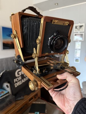
A fairly extreem example of tilt, swing and shift, to show whay a ruler at the base of the camera would be useless to determine bellows extension with.
We can literally "eyeball" how much exposure we need. It works regardless of the camera and lens used, because the amount of compensations boils down to one variable, and one variable only: magnification**. So how do we measure that?
We can simply measure the size of the projection on our ground glass, and compare it to the actual size of the subject. After that, simple look-up table will do. So now we know how to avoid using a tape measure on the bellows of our camera, can we also avoid bothering our subject with tape measure? As it turns out, yes.
Humans come with a built in ruler: Their eyes are on average 6.3cm, or 2.44 inch apart. If we take that as a given, then by the distance of the eyes as we see them on the ground glass, we can tell how much magnification happened.
So here’s my list of eye distances (rounded*) as projected onto the ground glass, and the corresponding exposure compensation in EV.
cm     inch   EV (additional stops)

0.75   1/3     1/3
1.66   2/3     2/3
2.5    1       1
3.75   1 1/2   1 1/3
5      2       1 2/3
6.30   2 1/2   2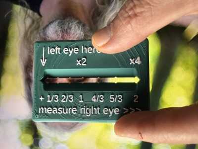
Measuring Eye distance on the ground glass. Here, just under 1 EV compensation was needed.
As you can see, there is a bit of a curve in these numbers: Closer when smaller, wider when larger. Under 1 EV compensation, the steps are around 1/3 of an inch, and above that, half an inch. Coincidentally, it’s easy to remember for those who were brought up using inches.
Those who's focus screens have a grid with 1cm squares could use those lines to measure the eye distance, and then use the above look-up table to find how much compensation is needed.
Those without a frame of reference, and access to a 3D printer, could install OpenSCAS and BOSL, and print this, with the top 2 layers in a different color. You could make a 2D print to, if you have such hardware with accurate size control. I do not.
OpenSCAD BOSL2 code
include <BOSL2/std.scad>
$fn = 180;
een=7.6;
twee=16.4;
drie=25.8;
vier=37.2;
vijf=49.1;
zes=63;
dikte=6;

difference(){cuboid([80,56.53,dikte], rounding=3);
    up(4){rotate([45,0,0]){cuboid([63,12,12], rounding=2);}}
// 4 sided "cylinders" to hack out the notches:
down(10){left(63/2){
right(0)cylinder(d=5.6, h=20, $fn=4);
right(een)cylinder(d=5.6, h=20, $fn=4);
right(twee)cylinder(d=5.6, h=20, $fn=4);
right(drie)cylinder(d=5.6, h=20, $fn=4);
right(vier)cylinder(d=5.6, h=20, $fn=4);
right(vijf)cylinder(d=5.6, h=20, $fn=4);
right(zes)cylinder(d=5.6, h=20, $fn=4);
}}
// my logo on the back
    logosize=0.66;
    rotate([0,180,0])             { //([0,180,0])
    scale([logosize,logosize,1]){  //1 = een dikte van 2mm
    translate([-72,-48.2+20,2.8]) {  //0.8 = 1 printlaagje boven nul
    //text shape
    translate([26.2,34.5,0])   {
        linear_extrude(0.4)
        text(">  v<",size=30);  }
    translate([71.6,62.5,0])   {
        rotate([0,0,180])       {
        linear_extrude(0.4)
        text("v", size=30);    }}
    }}}
}
//trail and error way to place the numbers. Do check if it lines up with the notches.
    translate([-32.3,18,2.8])   {
        linear_extrude(0.6)
        text("| left eye here",size=5);  }
    translate([-32.3,13,2.8])   {
        linear_extrude(0.6)
        text("|",size=5);  }
    translate([-33.73,10,2.8])   {
        linear_extrude(0.6)
        text("V           x2               x4",size=5);  }
    translate([-34,-14,2.8])   {
        linear_extrude(0.6)
        text("+ 1/3 2/3  1   4/3  5/3    2",size=4.5);  }
    translate([-34,-21.7,2.8])   {
        linear_extrude(0.6)
        text("measure right eye >>>",size=5);  }
//
Notes
*) The “exposure pentagram” would be more accurate: ISO, Aperture, Shutter time, Bellows compensation, development strength. The latter is in turn split up in three: concentration, duration and temperature. Granted that development is not happening during exposure, it is to be taken into account at that moment, because it’s at that point that you make decisions about contrast.
**) This also works because focal length hasn’t vanished completely from the equation, because it is incorporated in the F-value. If you’d had to compensate the aperture in mm, you’d still have to make calculations.
***) Unnecessarily precise list:
cm    inch  EV (additional stops)

0.76  0.3   0.33
1.64  0.65  0.66
2.58  1.    1
3.72  1.46  1.33
4.91  1.93  1.66
6.30  2.48  2